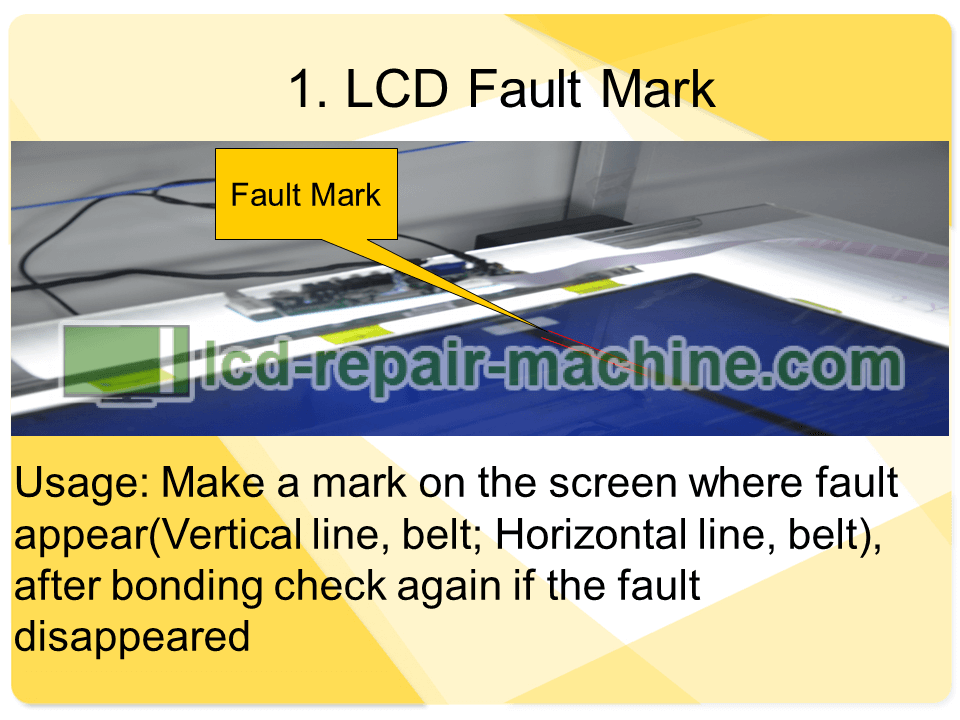
Usage: Make a mark on the screen where fault appear(Vertical line, belt; Horizontal line, belt), after bonding check again if the fault disappeared.
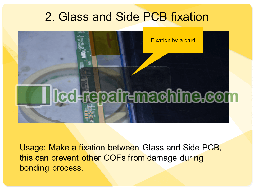
Usage: Make a fixation between Glass and Side PCB, this can prevent other COFs from damage during bonding process.
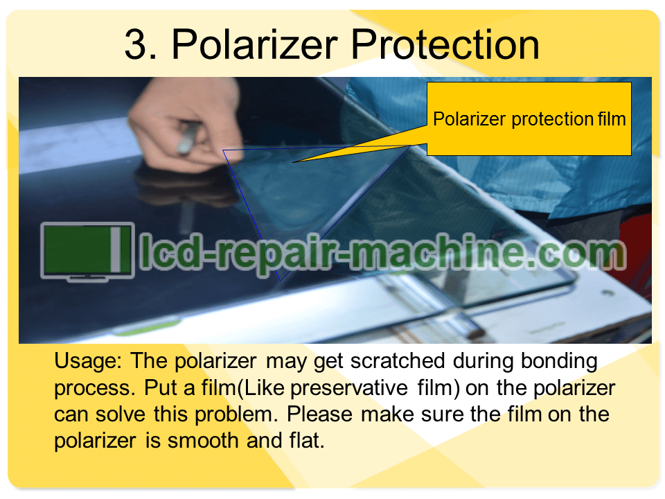
Usage: The polarizer may get scratched during bonding process. Put a film (Like preservative film) on the polarizer can solve this problem. Please make sure the film on the polarizer is smooth and flat.
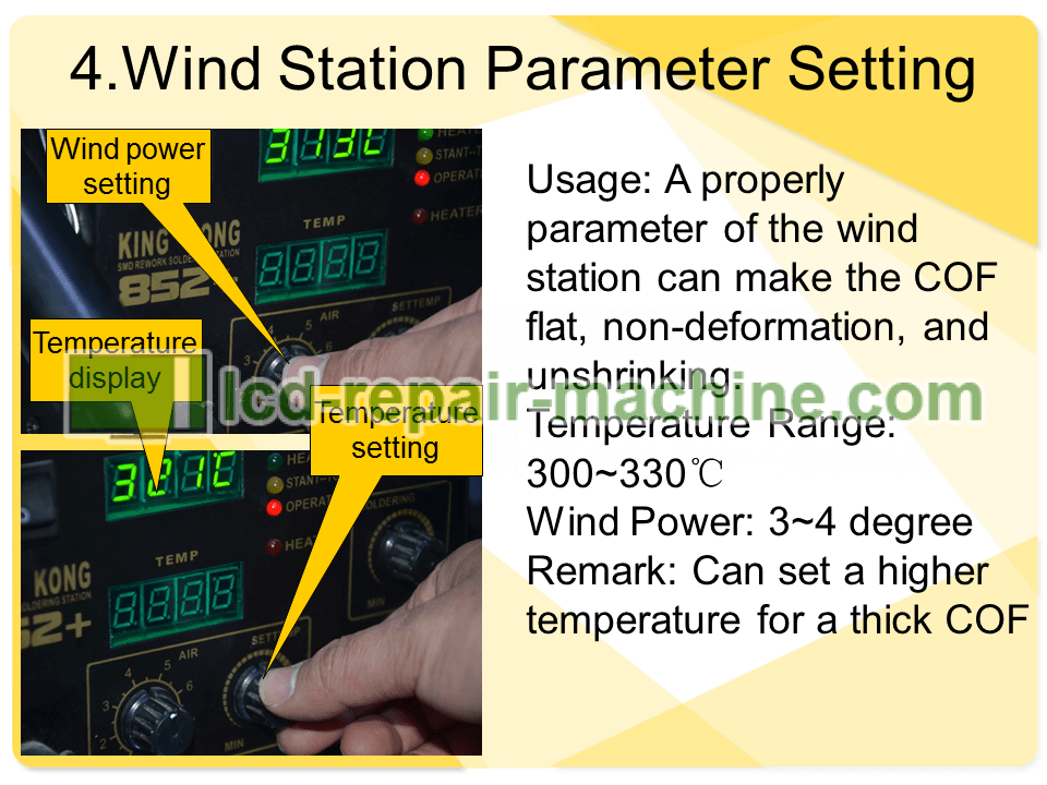
Usage: A properly parameter of the wind station can make the COF flat, non-deformation, and unshrinking during removing.
Temperature Range: 300-330?.
Wind Power: 3-4 degree.
Remark: Can set a higher temperature for a thick COF.
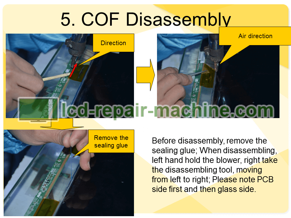
Before disassembly, remove the sealing glue; When disassembling, left hand hold the blower, right hand take the disassembling tool, moving from left to right; Please note PCB side disassembly first and then glass side.
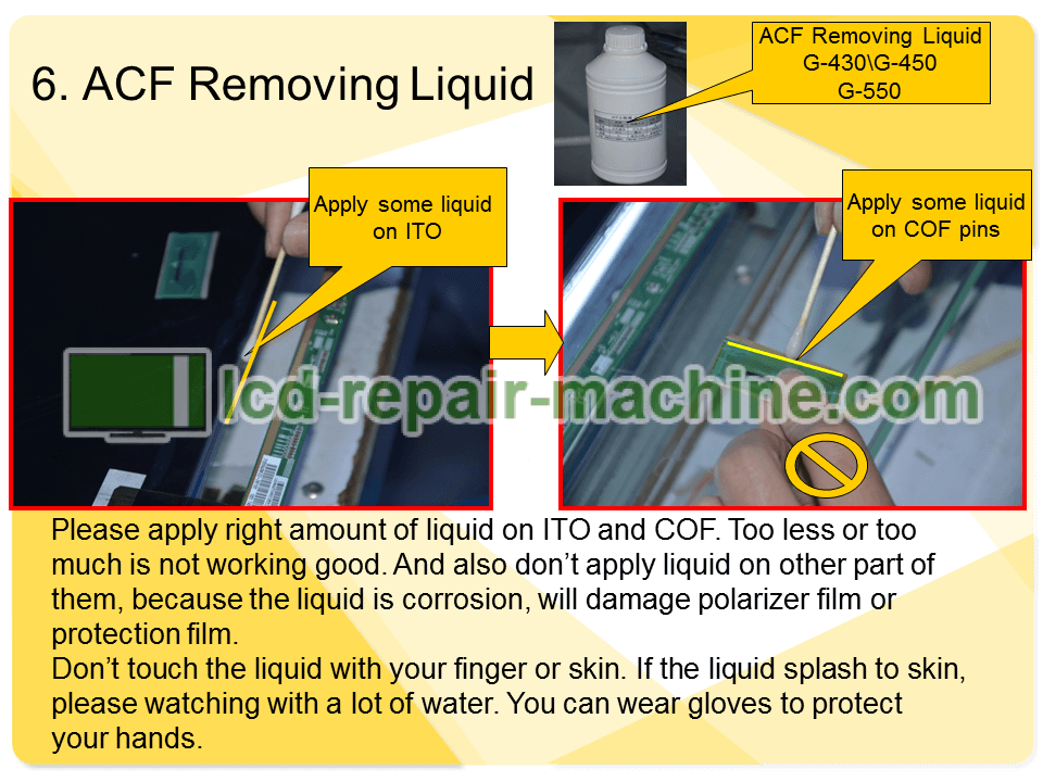
Please apply right amount of liquid on ITO Glass and COF. Too less or too much is not working good. And also don’t apply liquid on other part of them, because the liquid is corrosion, will damage the polarizer film or protection film.
Don’t touch the liquid with your finger or skin. If the liquid splash to skin, please watching with a lot of water. You can wear gloves to protect your hands.
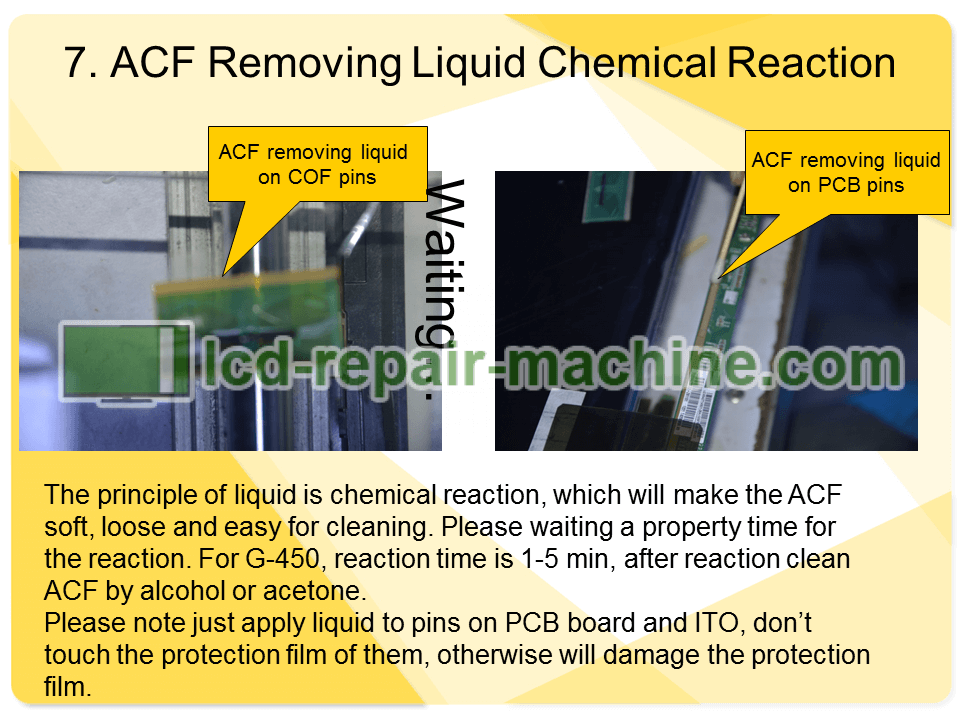
The principle of liquid is chemical reaction, which will make the ACF soft, loose and easy for cleaning. Please waiting a property time for the reaction. For G-450, reaction time is 1-5 min, after reaction clean ACF by alcohol or acetone.
Please note just apply liquid to pins and PCB board and ITO, don’t touch the protection film of them, otherwise will damage the protection film.
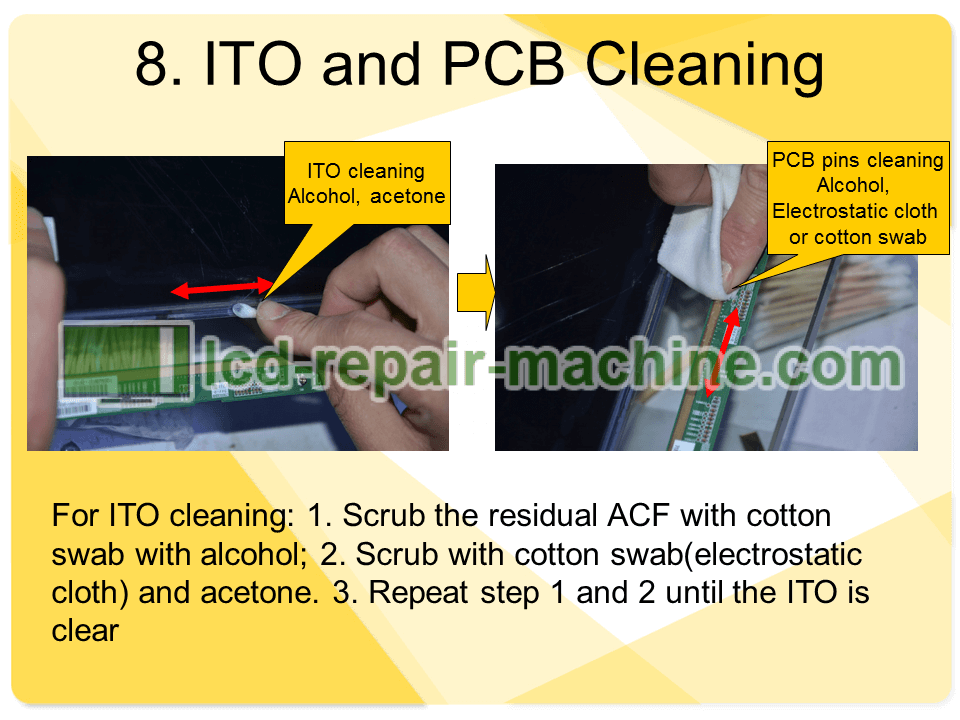
For ITO cleaning:
1. Scrup the residual ACF with cotton swab with alcohol;
2. Scrub with cotton swab(electrostatic cloth) and acetone.
3. Repeat step 1 and step 2 until the ITO is clear.
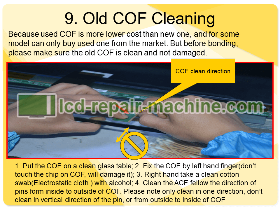
Because used COF is more lower cost than new one, and for some model can only buy used one from the market. But before bonding, please make sure the old COF is clean and not damaged.
1. Put the COF on a clean glass table;
2. Fix the COF by left hand finger (don’t touch the chip on COF, will damage it);
3. Right hand take a clean cotton swab (Electrostatic cloth) with alcohol;
4. Clean the ACF follow the direction of pins from inside to outside of COF. Please note only clean in one direction, don’t clear in vertical direction of the pin, or from outside to inside of COF.
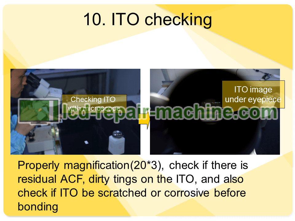
Property magnification (20*3), check if there is residual ACF or dirty tings on the ITO, and also check if ITO be scratched or corrosive before bonding.
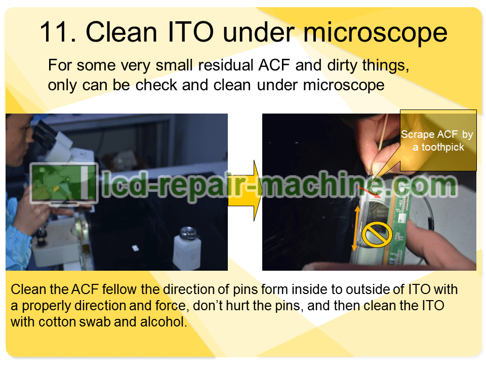
For some very small residual ACF and dirty tings, only can be check and clean under microscope.
Clean the ACF follow the direction of pins from inside to outside of ITO with a properly direction and force, don’t hurt the pins, and then clean the ITO with cotton swab and alcohol.
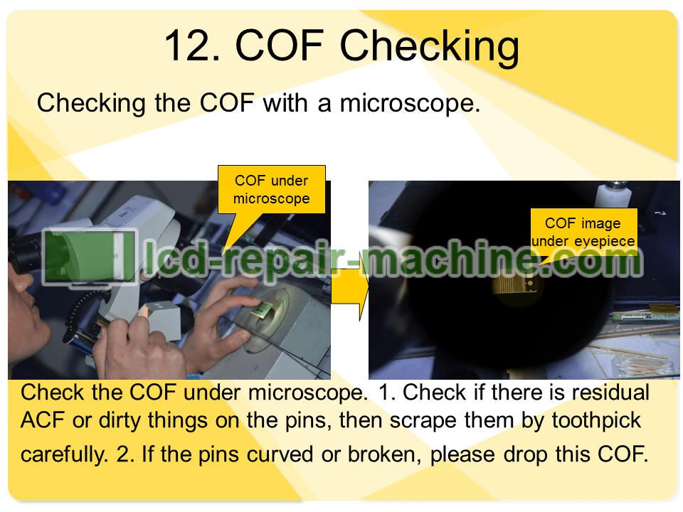
Check the COF under microscope.
1. Check if there is residual ACF or dirty things on the pins, then scrape them by toothpick carefully.
2. If the pins curved or broken, please drop this COF.
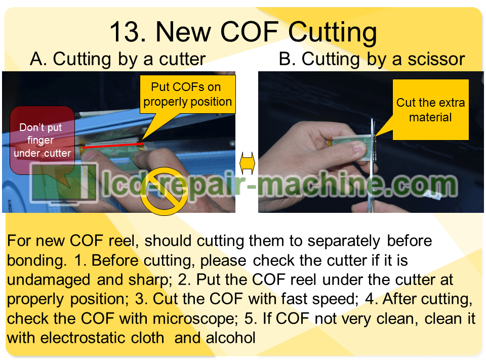
1. Before cutting, please check the cutter if it is undamaged and sharp;
2. Put the COF reel under the cutter at properly position;
3. Cut the COF with fast speed;
4. After cutting, check the COF with microscope;
5. If COF not very clean, clean it with electrostatic cloth and alcohol.
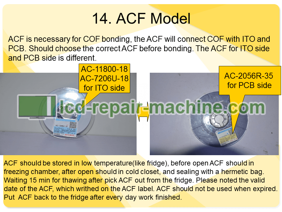
ACF is necessary for COF boding, the ACF will connect COF with ITO and PCB. Should choose the correct ACF before bonding. The ACF for ITO side and PCB side is different.
ACF should be stored in low temperature (like store in fridge), before open ACF should in freezing chamber, after open should in cold closet, and sealing with a hermetic bag. Waiting 15 min for thawing after pick ACF out from the fridge. Please noted the valid date of the ACF, which wrote on the ACF label. ACF should not be used when expired. Put ACF back to the fridge after every day work finished.
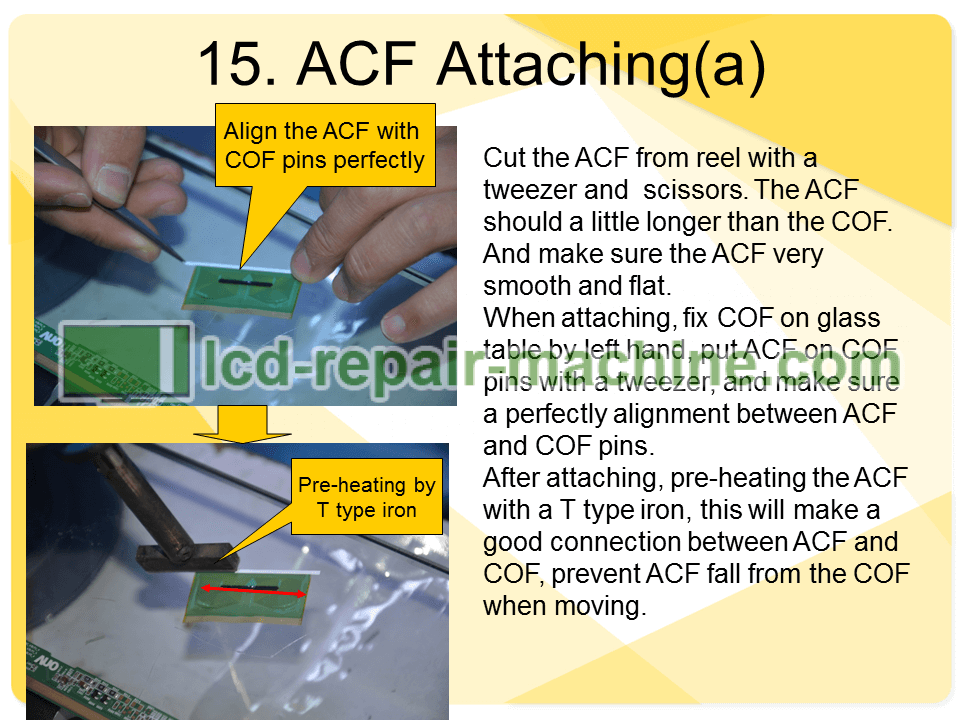
Cut the ACF from reel with a tweezers and scissors. The ACF should a little longer than the COF. And make sure the ACF very smooth and flat.
When attaching, fix COF on glass table by left hand, put ACF on COF pins with a tweezers, and make sure a perfectly alignment between ACF and COF pins.
After attaching, pre-heating the ACF with a T type iron, this will make a good connection between ACF and COF, prevent ACF fall from the COF when moving.
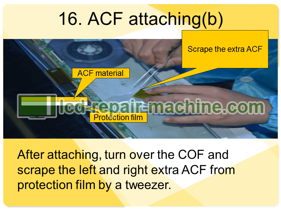
After attaching, turn over the COF and scrape the left and right extra ACF from protection film by a tweezers.
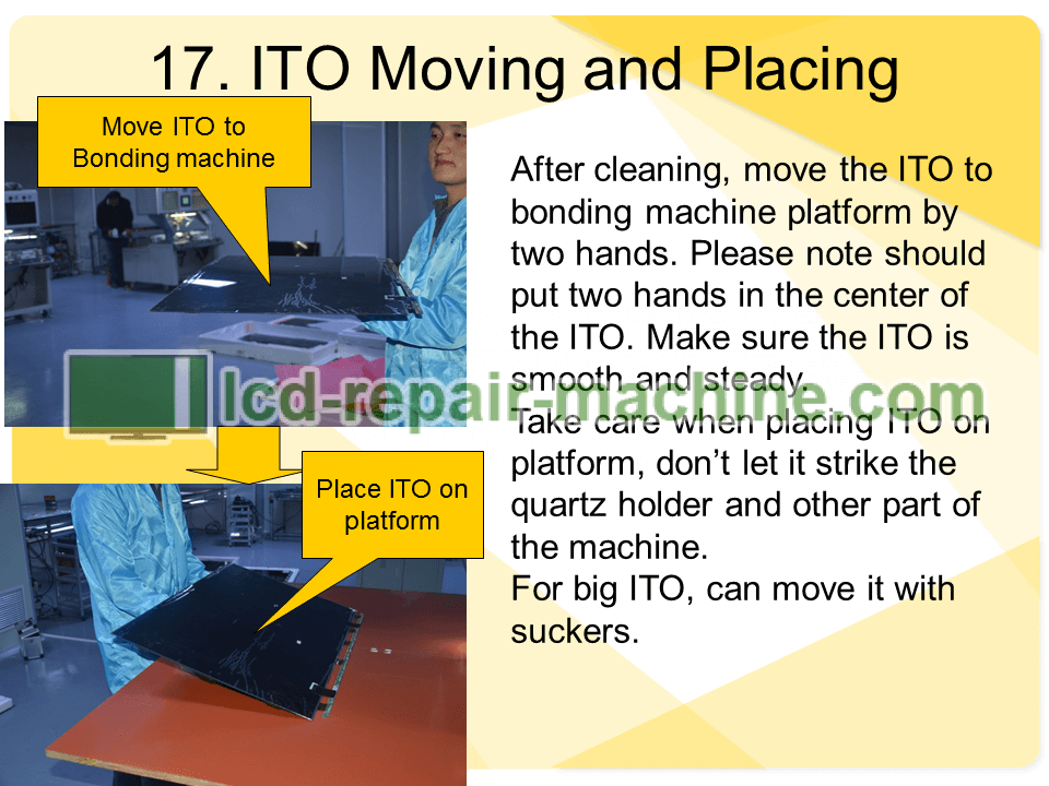
After cleaning, move the ITO to bonding machine platform by two hands. Please note should put two hands in the center of the ITO. Make sure the ITO is smooth and steady.
Take care when placing ITO on platform, don’t let it strike the quartz holder and other part of the machine.
For big ITO, can move it with suckers.
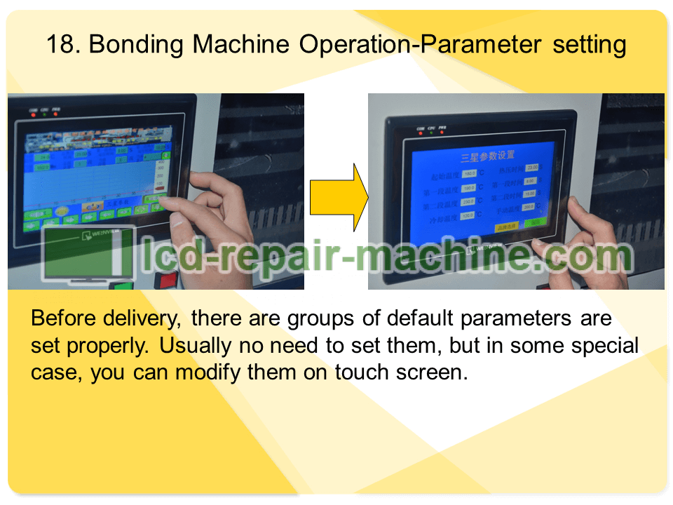
Before delivery, there are groups of default parameters are set properly. Usually no need to set them, but in some special case, you can modify them on touch screen.
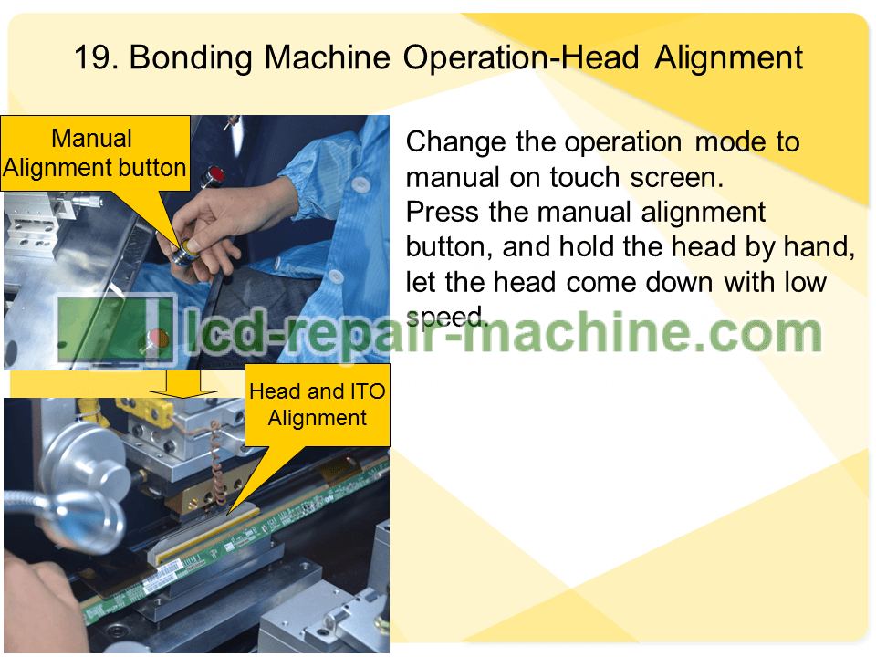
Change the operation mode to manual on touch screen.
Press the manual alignment button, and hold the head by hand, let the head come down with low speed.
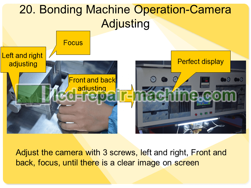
Adjust the camera with 3 screws, left and right, Front and back, focus, until there is a clear image on screen
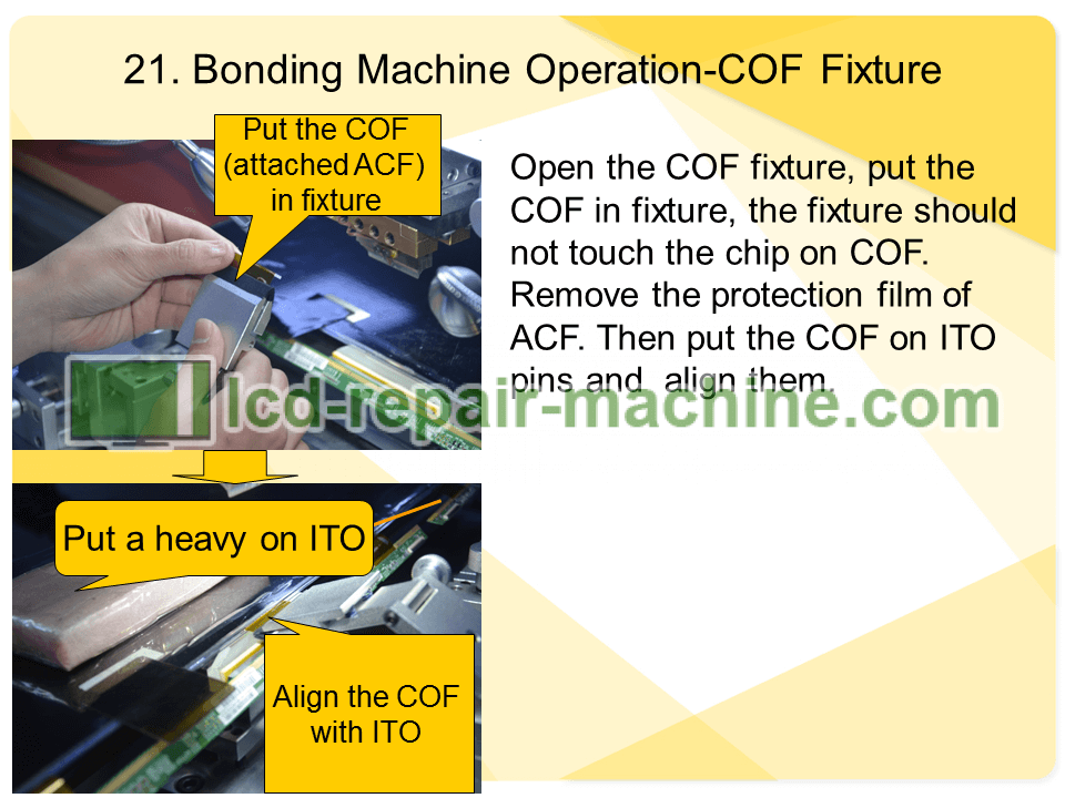
Open the COF fixture, put the COF in fixture, the fixture should not touch the chip on COF. Remove the protection film of ACF. Then put the COF on ITO pins and align them.
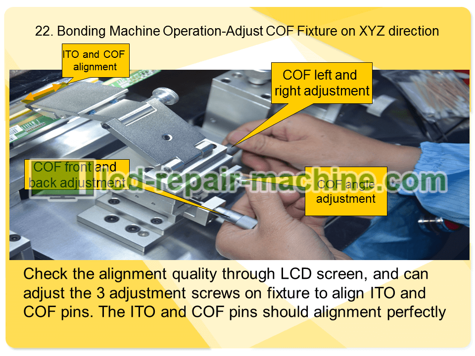
Check the alignment quality through LCD screen, and can adjust the 3 adjustment screws on fixture to align ITO and COF pins. The ITO and COF pins should alignment perfectly
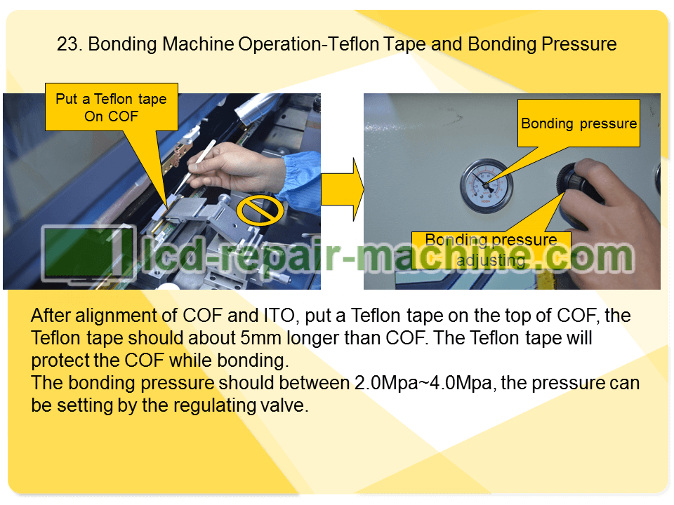
After alignment of COF and ITO, put a Teflon tape on the top of COF, the Teflon tape should about 5mm longer than COF. The Teflon tape will protect the COF while bonding.
The bonding pressure should between 2.0Mpa~4.0Mpa, the pressure can be setting by the regulating valve.
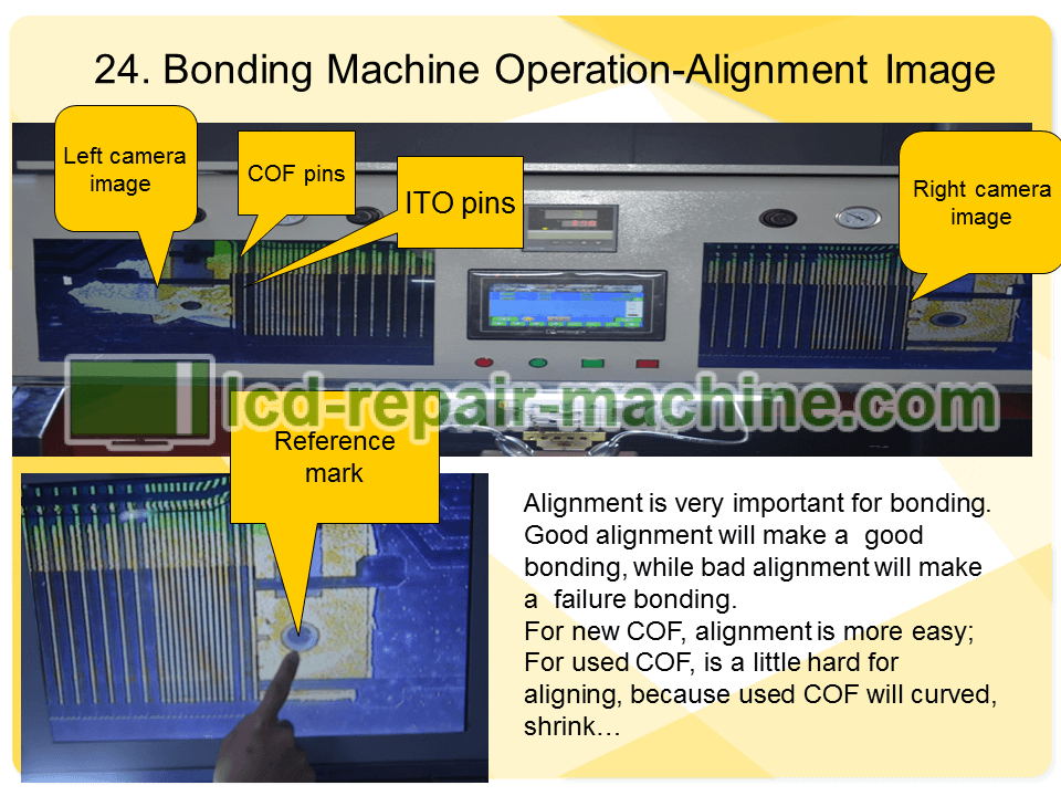
Alignment is very important for bonding. Good alignment will make a good bonding, while bad alignment will make a failure bonding.
For new COF, alignment is more easy;
For used COF, is a little hard for aligning, because used COF will curved, shrink…
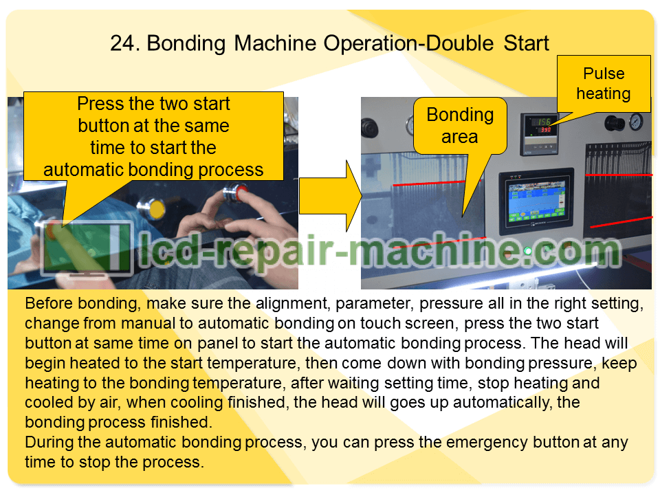
Before bonding, make sure the alignment, parameter, pressure all in the right setting, change from manual to automatic bonding on touch screen, press the two start button at same time on panel to start the automatic bonding process. The head will begin heated to the start temperature, then come down with bonding pressure, keep heating to the bonding temperature, after waiting setting time, stop heating and cooled by air, when cooling finished, the head will goes up automatically, the bonding process finished.
During the automatic bonding process, you can press the emergency button at any time to stop the process.
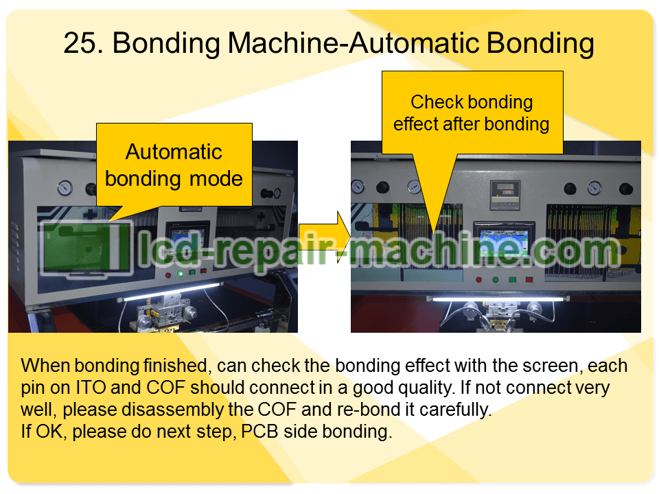
When bonding finished, can check the bonding effect with the screen, each pin on ITO and COF should connect in a good quality. If not connect very well, please disassembly the COF and re-bond it carefully.
If OK, please do next step, PCB side bonding.
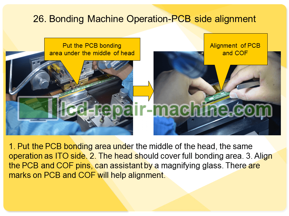
1. Put the PCB bonding area under the middle of the head, the same operation as ITO side.
2. The head should cover full bonding area.
3. Align the PCB and COF pins, can assistant by a magnifying glass. There are marks on PCB and COF will help alignment.
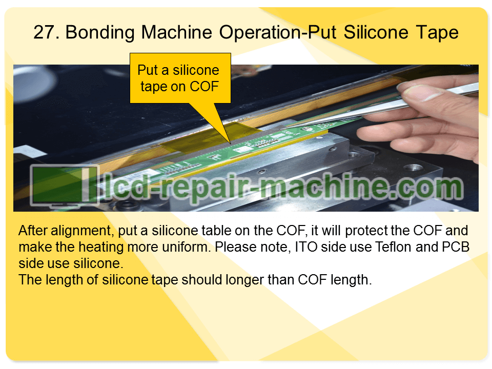
After alignment, put a silicone table on the COF, it will protect the COF and make the heating more uniform. Please note, ITO side use Teflon and PCB side use silicone.
The length of silicone tape should longer than COF length.
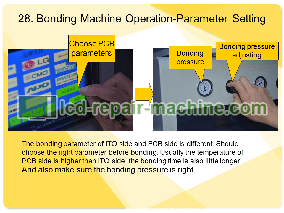
The bonding parameter of ITO side and PCB side is different. Should choose the right parameter before bonding. Usually the temperature of PCB side is higher than ITO side, the bonding time is also little longer.
And also make sure the bonding pressure is right.
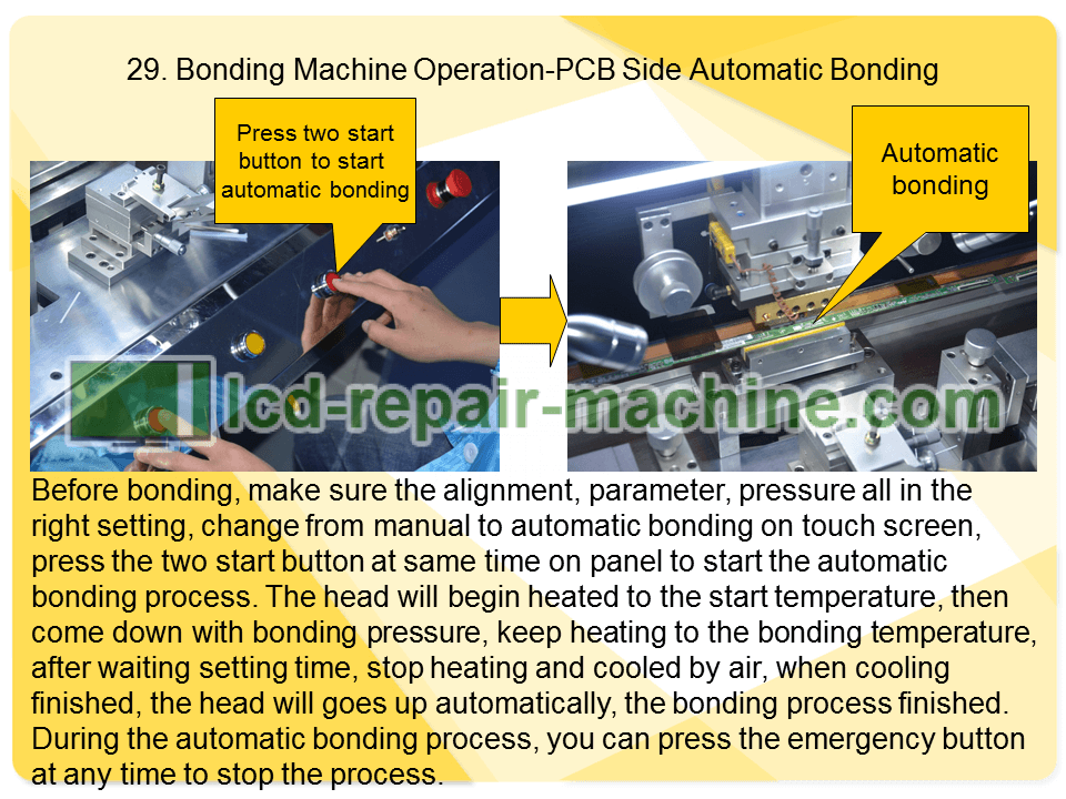
Before bonding, make sure the alignment, parameter, pressure all in the right setting, change from manual to automatic bonding on touch screen, press the two start button at same time on panel to start the automatic bonding process. The head will begin heated to the start temperature, then come down with bonding pressure, keep heating to the bonding temperature, after waiting setting time, stop heating and cooled by air, when cooling finished, the head will goes up automatically, the bonding process finished.
During the automatic bonding process, you can press the emergency button at any time to stop the process.
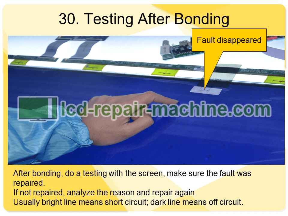
After bonding, do a testing with the screen, make sure the fault was repaired.
If not repaired, analyze the reason and repair again.
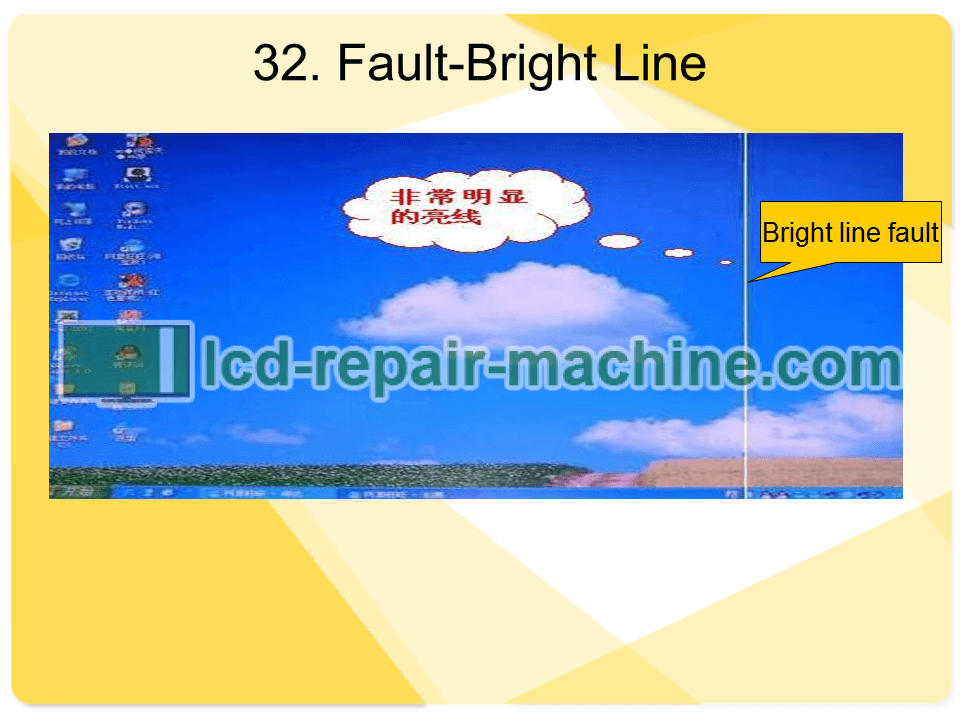
Usually bright line means short circuit; dark line means off circuit.
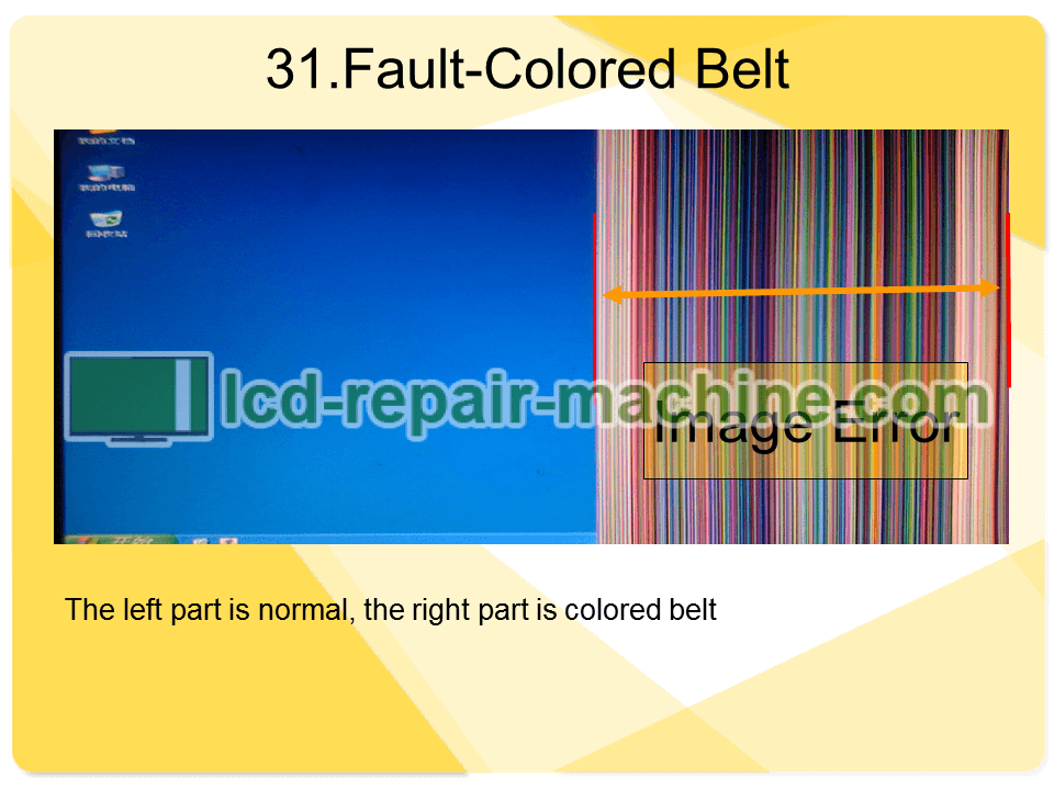
The left part is normal, the right part is colored belt
A quick view of how to replace LCD COF with a bonding machine